
 EMI Suppression Beads (2643250202)
Part Number: 2643250202
43 SHIELD BEAD
Explanation of Part Numbers:
– Digits 1&2 = product class,
– 3&4 = material grade and
– last digit 1= not burnished, 2 = burnished and 4 = Parylene coated.
– Beads with a “1” as the last digit of the part number are not burnished. Parts that are burnished to break the sharp edges have a “2” as the last digit.
– Upon request beads can be supplied with a Parylene coating. The last digit of the Parylene coated part is a “4”. The minimum coating thickness beads is 0.005 mm (0.0002″).
Fair-Rite offers a broad selection of ferrite EMI suppression beads with guaranteed minimum impedance specifications.
Our “Shield Bead Kit” (part number 0199000019) contains a selection of these beads.
For any EMI suppression bead requirement not listed here, feel free to contact our customer service for availability and pricing.
The C dimension, the bead length, can be modified to suit specific applications.
Weight: 2.5 (g)
| Dim | mm | mm tol | nominal inch | inch misc. |
| A | 6.35 | ±0.15 | 0.25 | _ |
| B | 2.95 | +0.45 | 0.125 | _ |
| C | 25.4 | ±0.75 | 1 | _ |

Chart Legend
+ Test frequency
• The column "H (Oe)" gives for each bead the calculated dc bias field in oersted for 1 turn and 1 ampere direct current. The actual dc H field in the application is this value of “H” times the actual NI (ampere-turn) product. For the effect of the dc bias on the impedance of the bead material, see figures 18-23 in the application note How to choose Ferrite Components for EMI Suppression.
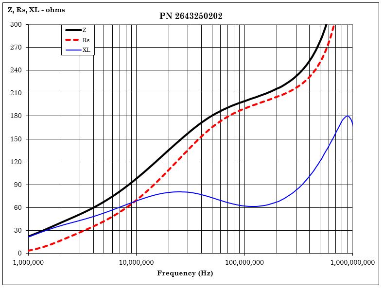
| Typical Impedance (Ω) | |
| 10 MHz | 98 |
| 25 MHz+ | 148 |
| 100 MHz+ | 200 |
| 250 MHz | 223 |
| Electrical Properties | |
| H(Oe) | 0.91 |
The column “H (Oe)” gives for each bead the calculated dc bias field in oersted for 1 turn and 1 ampere direct current. The actual dc H field in the application is this value of “H” times the actual NI (ampere-turn) product. For the effect of the dc bias on the impedance of the bead material, see figures 18-23 in the application note How to choose Ferrite Components for EMI Suppression.
Suppression beads are controlled for impedances only. Minimum impedance values are specified for the + marked frequencies. The minimum impedance is typically the listed impedance less 20%.
Single turn impedance tests for 73 and 43 material® beads are performed on the E4990A Impedance Analyzer. The 61 material beads are tested on the E4991A / HP4291B Impedance Analyzer. Beads are tested with the shortest practical wire length.
| Typical Impendance (Ω) | |
| 10 MHz | 83 |
| 25 MHz+ | 135 |
| 100 MHz+ | 200 |
| 250 MHz | 196 |