Rods (4078377511)
78 ROD
78 Material
Inductive Components
Open Magnetic Circuit
Printer Friendly Data Sheet
Catalog Drawing
3D Model
Check Stock

Part Number: 4078377511
78 ROD
Explanation of Part Numbers:
– Digits 1 & 2 = Product Class
– Digits 3 & 4 = Material Grade
Pressed Fair-Rite rods are used extensively in high-energy storage designs.
These rods can also be used for inductive components that require temperature stability or have to accommodate large dc bias requirements.
Figure 2 rods have a 0.6 mm (0.024) maximum chamfer on the end faces.
For frequency tuned rod designs see section Antenna/RFID Rods.
For any rod requirement not listed here, feel free to contact our customer service group for availability and pricing.
The A dimension can be centerless ground to tighter tolerances.
Weight: 24 (g)
| Dim | mm | mm tol | nominal inch | inch misc. |
| A | 9.5 | ±0.25 | 0.374 | _ |
| C | 70 | ±1.50 | 2.756 | _ |

Figure 1 shows the rod permeability as a function of the length to diameter ratio for the six materials available in rods.
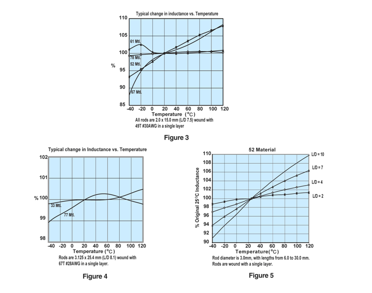
Figures 3, 4 and 5 illustrate typical temperature behavior of wound rods. Would rods in 33 and 77 material yield the best temperature stable inductors, see Figure 4. Both show a typical inductance change of <1% over the -40° to 120°C temperature range. The parts have a L/D ratio of 8.1. Lower ratios will change less. This is shown in detail in Figure 5 for the same 52 material but with the L/D ratio as the parameter. A lower ratio means a lower rod permeability but with improved temperature stability.

Wound Rod Inductance Calculations
To calculate the inductances of a wound rod the following formula can be used,
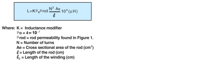
The inductance modifier is found in Figure 2. The ratio winding length divided by the rod length will give the inductance modifier. If the rod is totally wound the K=1. Shorter but centered winding will yield higher K values.
Using the rod 3061990871 as an example.
For this rod the length over diameter ratio is 8.33 and for 61 material Figure 1 gives a µrod of 29. The rod has an AE= 0.0707 cm² and ?=2.5 cm.
A winding of 80 turns of 30 AWG wire will yield a fully wound rod, therefore K=1.
Using the formula the calculated inductance is 65.96µH.
The measured values for both winding were 66.95 and 39.50µH respectively.
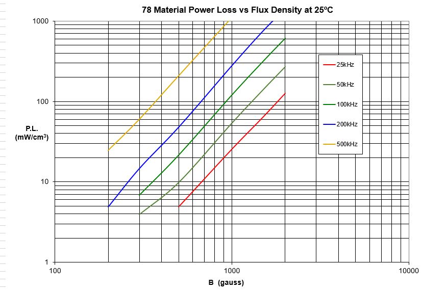
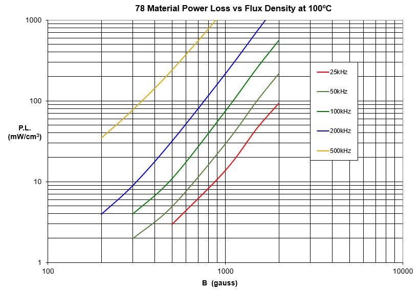
A MnZn ferrite specifically designed for power applications for frequencies up to 200 kHz and low loss inductive applications to 500 kHz.
Available in 78 material:
RFID Rods
Toroids
Mated Parts
78 Material Characteristics
| Property | Unit | Symbol | Value |
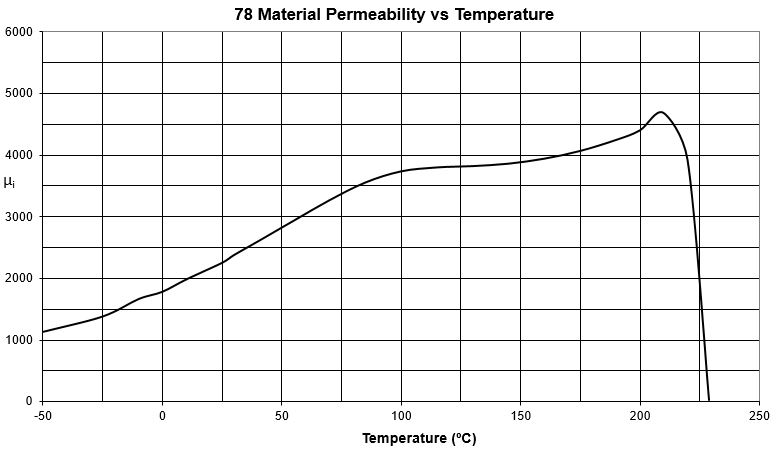
| Initial Permeability @ B < 10 gauss | µi | 2300 | |
| Flux Density @ Field Strength | Gauss Oersted |
B H |
4800 5 |
| Residual Flux Density | Gauss | Br | 1500 |
| Coercive Force | Oersted | Hc | 0.20 |
| Loss Factor @ Frequency | 10 -6 MHz |
Tan δ/ µi | 3 0.1 |
| Temperature Coefficient of Initial Permeability (20 -70°C) | %/°C | 1.0 | |
| Curie Temperature | °C | Tc | >200 |
| Resistivity | ohm-cm | ρ | 200 |
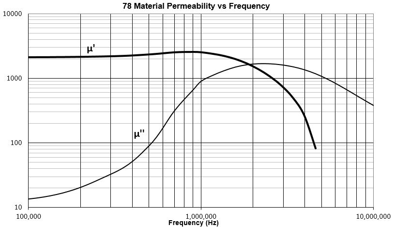
**** Characteristic curves are measured on standard Toroids (18/10/6 mm) at 25°C and 10 kHz unless otherwise indicated. Impedance characteristics are measured on standard shield beads (3.5/1.3/6.0 mm) unless otherwise indicated.
Material Safety Data Sheet (MSDS)
Click here to download Complex Permeability vs. Frequency (CSV)


Ferrite Material Constants
Storage and Operating Temperature
Printer Friendly Data Sheet - Download as pdf file